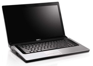
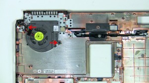
In this Dell laptop tutorial we are going to show you how to install and replace the Sub-Woofer Speaker on your Dell Studio 1555 / 1557 / 1558 laptop. These installation instructions have be made into 20 easy to follow printable steps. We have also create a video tutorial that shows you how to install your Dell Studio 1555 / 1557 / 1558 Sub-Woofer Speaker.
Before you begin

Dell repair manual service precautions
Tools needed for this laptop repair
- 1 x small phillips head screw driver
- 1 x small plastic scribe
|
|
DIY Discount - Parts-People.com offers 5% off to all DO-IT-YOURSELFERS!
Use this coupon code to save 5% off these parts DIYM514
|
Video tutorial repair manual
Installation and Removal Instructions
Dell Studio 1555 / 1557 / 1558 Sub-Woofer Speaker
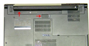

Step 1
- Slide the battery latch to the right.
- Slide the battery out of the laptop.
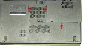

Step 2
- Unscrew the 3 retaining screws on the Access Door.
- Lift the door away from the laptop base.
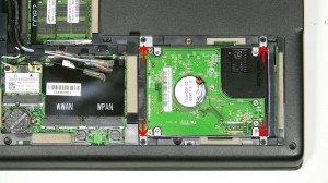

Step 3
- Unscrew the (4) 3mm x 3mm hard drive screws.
- Slide the hard drive to the right and lift it out of the laptop.
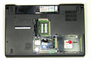

Step 4
- Remove the 2mm x 3mm screw under the hard drive.
- Unscrew the (7) 2.5mm x 5mm screws on the base of the laptop.
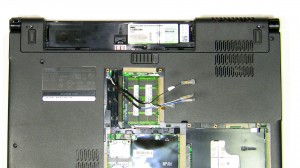

Step 5
- Unplug the antenna cables and loosen them from their routing channels.
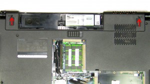

Step 6
- Unscrew the (2) 2.5mm x 5mm bottom hinge screws.
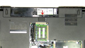

Step 7
- Remove the 2mm x 3mm screw under the battery.
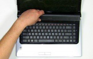

Step 8
- Unsnap the media control cover from the palm rest starting at the back near to the screen.
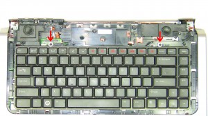

Step 9
- Unscrew the (2) 2mm x 3mm screws for the keyboard.
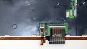

Step 10
- Carefully lift the keyboard away form the base and turn it over. If you pull it to hard you risk breaking the keyboard cable connector on the motherboard.
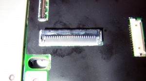

Step 11
- Pivot the keyboard cable latch and the back light cable latch up and unplug the cables.
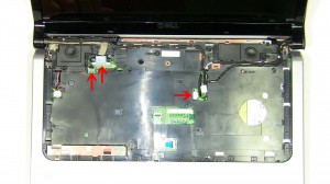

Step 12
- disconnect the LCD display cable and the power button cable.
- Pull the antenna cables through the base and loosen all of the cables from their routing channels.
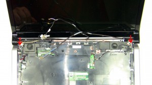

Step 13
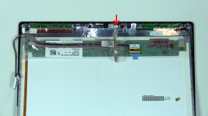
- Open the display wide and unscrew the (2) 2.5mm x 5mm screws that hold the display to top of the base.
- Lift the display from base assembly.
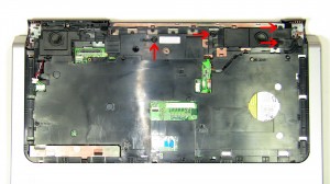

Step 14
- Remove the (4) 2mm x 3mm screws at the top of the palm rest.
- Unscrew the (6) 2.5mm x 5mm screws that sit under the keyboard.
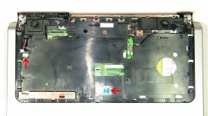

Step 15
- Unplug the speaker cable and the touchpad cable.
- Carefully unsnap the palmrest from the base and the motherboard.
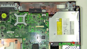

Step 16
- Unscrew the 2.5mm x 5mm optical drive screw.
- Remove the optical drive from the motherboard.
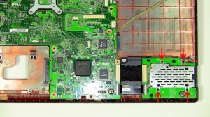

Step 17
- Unscrew the (4) 2.5mm x 5mm screws for the ExpressCard Slot and Media Card Reader IO Circuit Board.
- Unplug the ExpressCard Slot and Media Card Reader IO Circuit Board cables from the motherboard.
- Remove the ExpressCard Slot and Media Card Reader IO Circuit Board from the base.
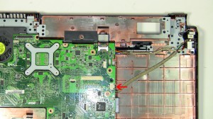

Step 18
- Unplug the USB Port cable.
- Unplug the DC Jack cable.
- Unplug the fan and sub-woofer cables.
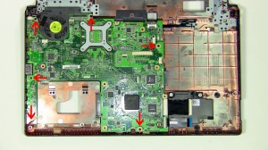

Step 19
- Unscrew the (6) 2.5mm x 5mm Motherboard screws.
- Remove the motherboard from the base of the laptop.
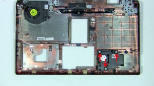

Step 20
- Unscrew the (3) Sub-woofer screws.
- Lift the Sub-woofer from the base.
|
|
DIY Discount - Parts-People.com offers 5% off to all DO-IT-YOURSELFERS!
Use this coupon code to save 5% off these parts DIYM514
|

 Laptop & Tablet Parts