 Laptop & Tablet Parts
 Desktop & All-in-one Parts
 Dell Server Parts


In this Dell laptop tutorial we are going to show you how to install and replace the Power Button and Cable on your Dell Studio 1555 / 1557 / 1558 laptop. These installation instructions have be made into 16 easy to follow printable steps. We have also create a video tutorial that shows you how to install your Dell Studio 1555 / 1557 / 1558 Power Button and Cable.
Before you begin
 Please take the time read the following safety guidelines when working on static sensitive electrical components.
Dell repair manual service precautions
Tools needed for this laptop repair
- 1 x small phillips head screw driver
- 1 x small plastic scribe
Studio 1558 Power Button
Studio 1558 Power Button
|
Eligible for $5.00 Economy Shipping. Only 7 left in stock - order soon. 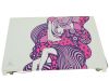
$19.95
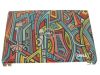
THE MUSE IN PURPLE - Dell Studio 1555 1557 1558 15.6" LCD Back Cover Lid Top with Hinges - DCGYP Eligible for $5.00 Economy Shipping. Only 9 left in stock - order soon. 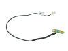
Eligible for $5.00 1st Class Shipping. In Stock DIY Discount - Parts-People.com offers 5% off to all DO-IT-YOURSELFERS!
Use this coupon code to save 5% off these parts DIYM514
|
Video tutorial repair manual
Installation and Removal Instructions
Dell Studio 1555 / 1557 / 1558 Power Button and Cable
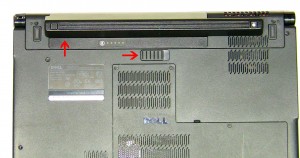
Step 1
- Slide the battery latch to the right.
- Slide the battery out of the laptop.
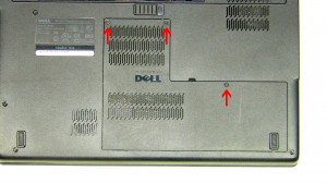
Step 2
- Unscrew the 3 retaining screws on the Access Door.
- Lift the door away from the laptop base.
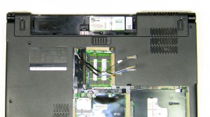
Step 3
- Unplug the antenna cables and loosen them from their routing channels.
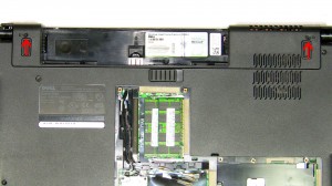
Step 4
- Unscrew the (2) 2.5mm x 5mm bottom hinge screws.
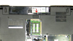
Step 5
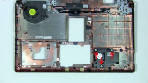
- Remove the 2mm x 3mm screw under the battery.
Step 6
- Unsnap the media control cover from the palm rest starting at the back near to the screen.
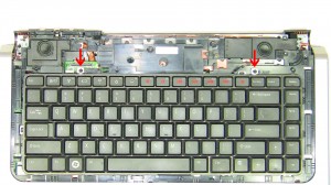
Step 7
- Unscrew the (2) 2mm x 3mm screws for the keyboard.
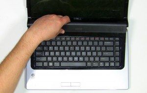
Step 8
- Carefully lift the keyboard away form the base and turn it over. If you pull it to hard you risk breaking the keyboard cable connector on the motherboard.
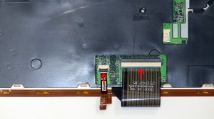
Step 9
- Pivot the keyboard cable latch and the back light cable latch up and unplug the cables.
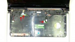
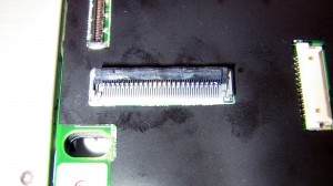
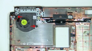
Step 10
- disconnect the LCD display cable and the power button cable.
- Pull the antenna cables through the base and loosen all of the cables from their routing channels.
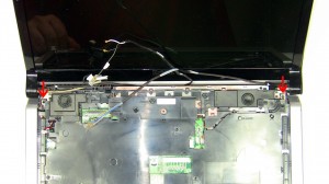
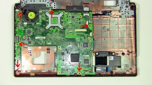
Step 11
- Open the display wide and unscrew the (2) 2.5mm x 5mm screws that hold the display to top of the base.
- Lift the display from base assembly.
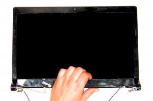
Step 12
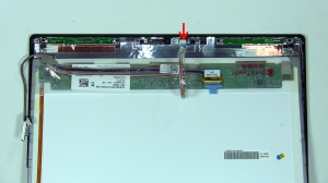
- Unsnap the LCD Display Bezel, starting from the bottom and working around the edges.
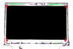
Step 13
- Unscrew the (4) 2.5mm x 5mm at the corners of the screen.
Step 14
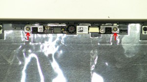
- Carefully lift the screen and unplug the camera cable.
Step 15
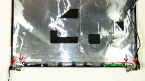
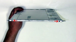
- Unscrew the (4) 2.5mm x 5mm left and right hinge screws.
- Remove the left and right hinges from the LCD back assembly.
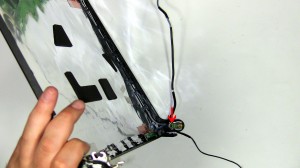
Step 16
- Unscrew the 2mm x 3mm screw holding the power button.
Studio 1558 Power Button
Studio 1558 Power Button
|
|
Eligible for $5.00 Economy Shipping. Only 7 left in stock - order soon.
$19.95
THE MUSE IN PURPLE - Dell Studio 1555 1557 1558 15.6" LCD Back Cover Lid Top with Hinges - DCGYP Eligible for $5.00 Economy Shipping. Only 9 left in stock - order soon.
Eligible for $5.00 1st Class Shipping. In Stock DIY Discount - Parts-People.com offers 5% off to all DO-IT-YOURSELFERS!
Use this coupon code to save 5% off these parts DIYM514
|

2 Responses to Dell Studio 1555 / 1557 / 1558 Power Button and Cable Removal and Installation