Laptop & Tablet Parts
 Desktop & All-in-one Parts
 Dell Server Parts


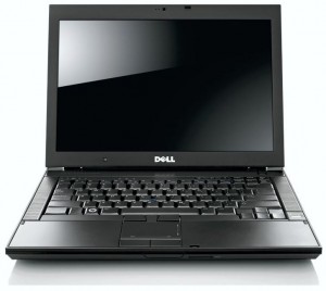
In this Dell laptop tutorial we are going to show you how to install and replace the USB Audio Circuit Board on your Dell Latitude E6400 laptop. These installation instructions have be made into 27 easy to follow printable steps. We have also create a video tutorial that shows you how to install your Dell Latitude E6400 USB Audio Circuit Board.
Before you begin
 Please take the time read the following safety guidelines when working on static sensitive electrical components.
Dell repair manual service precautions
Tools needed for this laptop repair
- 1 x small phillips head screw driver
- 1 x small plastic scribe
Latitude E6400 Audio Circuit Board
Latitude E6400 Audio Circuit Board
|
Eligible for $5.00 1st Class Shipping. In Stock 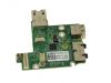
Eligible for $5.00 1st Class Shipping. In Stock 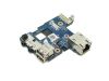
$4.95
Dell Latitude E6400 / E6400 ATG / Precision M2400 IO Circuit Audio Board for *Discrete Motherboard Eligible for $5.00 1st Class Shipping. In Stock DIY Discount - Parts-People.com offers 5% off to all DO-IT-YOURSELFERS!
Use this coupon code to save 5% off these parts DIYM514
|
Video tutorial repair manual
Installation and Removal Instructions
Dell Latitude E6400 USB Audio Circuit Board
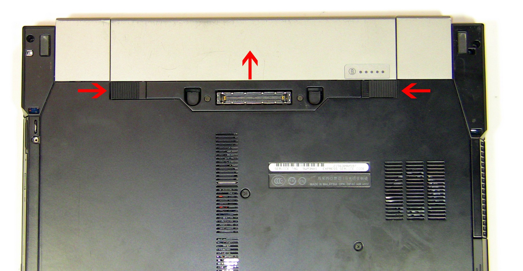
Step 1
- Slide the battery latches over and slide the battery up.
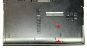
Step 2
- Remove the (2) 3mm x 3mm hard drive screws.
- Slide the hard drive out of the laptop.
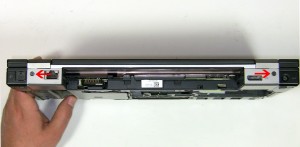
Step 3
- Unscrew the 2mm x 3mm optical drive locking screw.
- Press in the optical drive latch to get it to eject.
- Pull the optical drive latch to slide the drive out of the laptop.
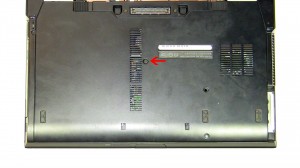
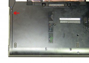
Step 4
- Loosen the access panel door cover screw.
- Slide the door down and lift it off of the laptop.
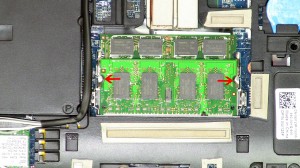
Step 5
- Separate the clips on the left and right side of the memory stick until the memory pivots up to a 45 degree angle.
- Slide the memory out of the memory slot.
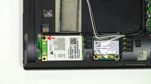
Step 6
- Disconnect the WWAN antenna cables.
- Remove the 2mm x 3mm WWAN card screw.
- Remove the WWAN card from the motherboard.
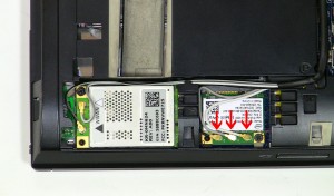
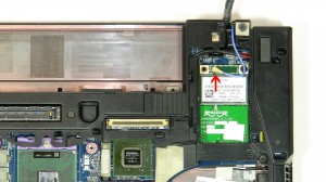
Step 7
- Disconnect the WLAN antenna cables.
- Remove the 2mm x 3mm WLAN card screw.
- Remove the WLAN card from the motherboard.
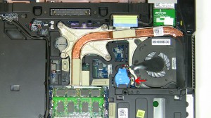
Step 8
- Unplug the fan.
- Loosen the 4 heat sink screws.
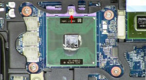
Step 9
- Using a flat head screw driver, turn the CPU locking screw counterclockwise to unlock the CPU.
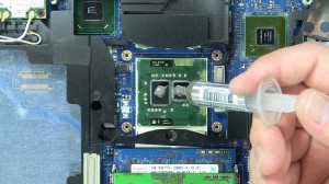
Step 10
- Installation note 1: Make sure to replace thermal compound or thermal pads on the CPU and heatsink.
- Installation note 2: Tighten the heatsink screws in the order listed on the heatsink.
- **This image is used only as an example.**
Step 11
- Under the battery, loosen the 3 clips by sliding them to the left.
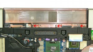
Step 12
- Unscrew the (2) 2.5mm x 5mm screws on the left and right hinge covers.
- Slide the hinge covers up and lift them off of the laptop base.
Step 13
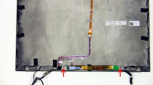
- Disconnect the WPAN antenna cables.
- Remove the 2mm x 3mm WPAN card screw.
- Remove the WPAN card from the motherboard.
Step 14
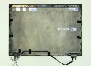
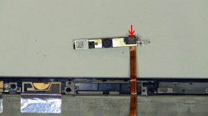
- Loosen the antenna cables and disconnect the LCD cable.
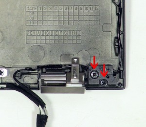
- Unscrew the (2) 2.5mm x x5mm hinge screws.
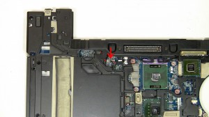
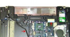
Step 15
- Unplug the DC jack cable.
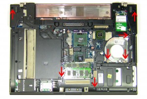
Step 16
- Unscrew the (7) 2.5mm x 5mm palm rest screws on the bottom of the laptop.
Step 17
- Turn the laptop over and open it up.
- Lift under the LED cover to remove it from the laptop.
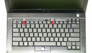
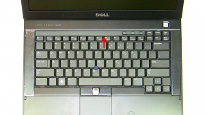
Step 18
- Remove the (2) 2mm x 3mm screws.
- Using the tab at the top of the keyboard, slide the keyboard up and lift the keyboard away from the laptop.
Step 19
- Disconnect the 4 palmrest cables.
Step 20
- Unscrew the (4) 2.5mm x 5mm palm rest screws on the top of the laptop.
- Lift the palmrest off of the laptop base.
Step 21
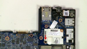
- Remove the 2mm x 3mm modem screw.
- Lift the modem off of the motherboard.
- Unplug the modem cable.
Step 22
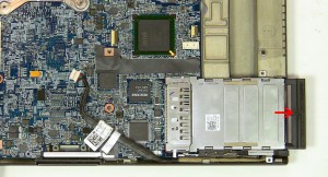
- Remove the filler card.
- Remove the (2) 2mm x 3mm screws.
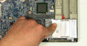
Step 23
- To remove the cage you will have to press down on the center of the cage and lift the back edge at the same time.
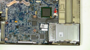
Step 24
- Unplug the 1394 cable.
- Remove the protective tape.
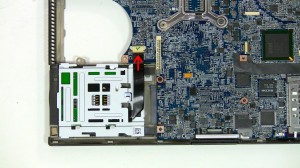
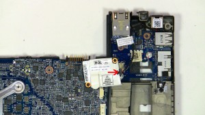
Step 25
- Unplug the smart card cable.
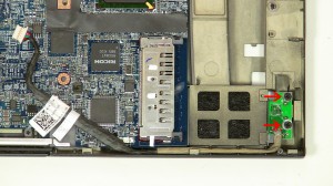
Step 26
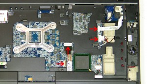
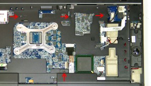
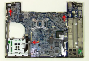
- Remove the (3) 2.5mm x 5mm motherboard screws.
- Carefully lift the motherboard out of the base, starting at the back. The USB/NIC circuit board will disconnect from the motherboard and stay in the base assembly.
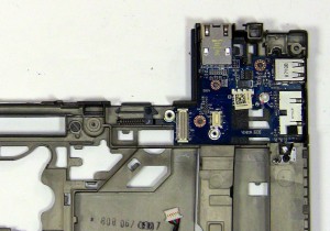
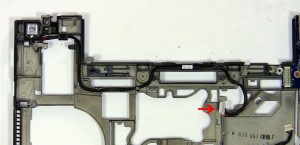
Step 27
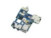
- Remove the USB audio circuit board from the base.
Latitude E6400 Audio Circuit Board
Latitude E6400 Audio Circuit Board
|
|
Eligible for $5.00 1st Class Shipping. In Stock
Eligible for $5.00 1st Class Shipping. In Stock
$4.95
Dell Latitude E6400 / E6400 ATG / Precision M2400 IO Circuit Audio Board for *Discrete Motherboard Eligible for $5.00 1st Class Shipping. In Stock DIY Discount - Parts-People.com offers 5% off to all DO-IT-YOURSELFERS!
Use this coupon code to save 5% off these parts DIYM514
|