Laptop & Tablet Parts
 Desktop & All-in-one Parts
 Dell Server Parts


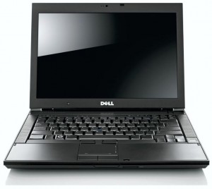
In this Dell laptop tutorial we are going to show you how to install and replace the LCD Back Cover Assembly on your Dell Latitude E6400 laptop. These installation instructions have be made into 11 easy to follow printable steps. We have also create a video tutorial that shows you how to install your Dell Latitude E6400 LCD Back Cover Assembly .
Before you begin
 Please take the time read the following safety guidelines when working on static sensitive electrical components.
Dell repair manual service precautions
Tools needed for this laptop repair
- 1 x small phillips head screw driver
- 1 x small plastic scribe
Latitude E6400 LCD Back Cover
Latitude E6400 LCD Back Cover
|
Eligible for $5.00 Economy Shipping. Only 3 left in stock - order soon. 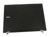
Eligible for $5.00 Economy Shipping. Only 6 left in stock - order soon. 
Eligible for $5.00 Economy Shipping. In Stock DIY Discount - Parts-People.com offers 5% off to all DO-IT-YOURSELFERS!
Use this coupon code to save 5% off these parts DIYM514
|
Video tutorial repair manual
Installation and Removal Instructions
Dell Latitude E6400 LCD Back Cover Assembly
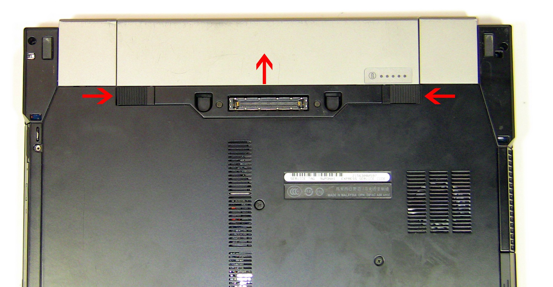
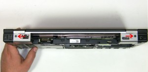
Step 1
- Slide the battery latches over and slide the battery up.
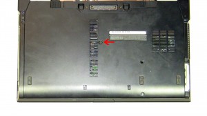
Step 2
- Loosen the access panel door cover screw.
- Remove the (2) 3mm x 3mm hard drive screws
- Slide the door down and lift it off of the laptop.
Step 3
- Unscrew the (2) 2.5mm x 5mm screws on the left and right hinge covers.
- Slide the hinge covers up and lift them off of the laptop base.
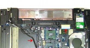
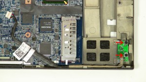
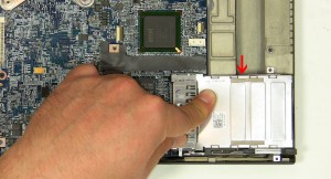
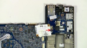
Step 4
- Loosen the antenna cables and disconnect the LCD cable.
- Unscrew the (2) 2.5mm x x5mm hinge screws.
- Turn the laptop over, open the LCD, and lift it off of the base.
![**Tech note: The E6400 has multiple screen types and configurations(CCFL, LED, with and without camera, Electronic Privacy View [EPV], and different resolutions for the screens). Before purchasing LCD back assemblies, LCD bezels, LCD Cables, and LCD screens you should confirm the part numbers.](https://www.parts-people.com/blog/wp-content/uploads/2011/09/E6400Bezel-300x210.jpg)
Step 5
- Carefully remove the bezel by unsnapping it around the edge of the screen. Go slowly, they can be difficult to remove.
- **Tech note: The E6400 has multiple screen types and configurations(CCFL, LED, with and without camera, Electronic Privacy View [EPV], and different resolutions for the screens). Before purchasing LCD back assemblies, LCD bezels, LCD Cables, and LCD screens you should confirm the part numbers.
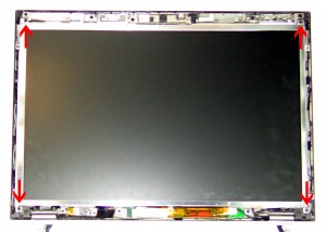
Step 6
- Remove the (4) 2.5mm x 5mm LCD screen screws.
- Lift the LCD screen away from the bask assembly and lay it face down.
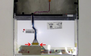
Step 7
- Disconnect the LCD ribbon cable.
- Unplug the LCD inverter or converter.
Step 8
- Pivot the left hinge up and slide the LCD ribbon cable out.
- Remove the (2) 2mm x 3mm screws on the Ambient Light Sensor (ALS).
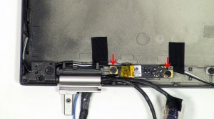
Step 9
- Unplug the LCD ribbon cable from the inverter.
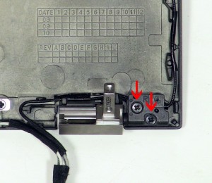
- Unscrew the camera screw.
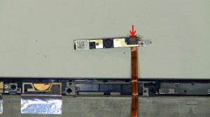
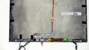
Step 10
- Slide the camera up and unplug the camera cable.
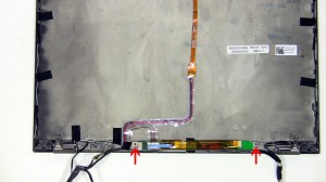
- Remove the LCD cable from the back assembly.
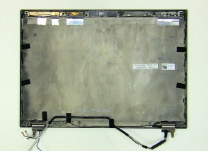
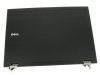
Step 11
- The remaining piece is the LCD back cover assembly.
Latitude E6400 LCD Back Cover
Latitude E6400 LCD Back Cover
|
|
Eligible for $5.00 Economy Shipping. Only 3 left in stock - order soon.
Eligible for $5.00 Economy Shipping. Only 6 left in stock - order soon.
Eligible for $5.00 Economy Shipping. In Stock DIY Discount - Parts-People.com offers 5% off to all DO-IT-YOURSELFERS!
Use this coupon code to save 5% off these parts DIYM514
|