Laptop & Tablet Parts
 Desktop & All-in-one Parts
 Dell Server Parts


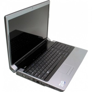
In this Dell laptop tutorial we are going to show you how to install and replace the Motherboard on your Dell Studio 17 (1735 / 1737) laptop. These installation instructions have be made into 27 easy to follow printable steps. We have also create a video tutorial that shows you how to install your Dell Studio 17 (1735 / 1737) Motherboard .
Before you begin
 Please take the time read the following safety guidelines when working on static sensitive electrical components.
Dell repair manual service precautions
Tools needed for this laptop repair
- 1 x small phillips head screw driver
- 1 x small plastic scribe
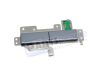
Studio 1737 Mouse Button
Studio 1737 Mouse Button
|
Eligible for $5.00 1st Class Shipping. In Stock 
Eligible for $5.00 1st Class Shipping. In Stock 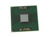
Eligible for $5.00 1st Class Shipping. Only 0 left in stock - order soon. DIY Discount - Parts-People.com offers 5% off to all DO-IT-YOURSELFERS!
Use this coupon code to save 5% off these parts DIYM514
|
Video tutorial repair manual
Installation and Removal Instructions
Dell Studio 17 (1735 / 1737) Motherboard
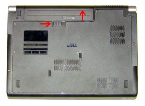
Step 1
- Slide the battery latch to the right.
- Slide the battery up and lift it away from the laptop.
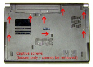
Step 2
- Loosen the 8 retaining screws (cannot be removed).
- Slide the access door up an off of the laptop.
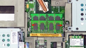
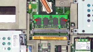
Step 3
- Separate the 2 retaining clips until the memory stick lifts up.
- Slide the memory stick out of the memory slot.
- Repeat the process for the bottom memory stick.
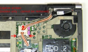
Step 4
- Loosen the 3 heat sink screws (cannot be removed).
- Remove the heat sink from the laptop.
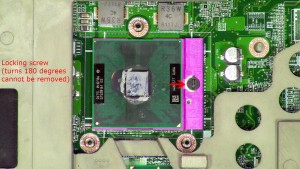
Step 5
- Turn the CPU locking screw counter-clockwise 180 degrees.
- Lift the CPU out of the CPU socket.
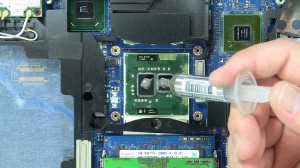
Step 6
- Installation note 1: Make sure to replace thermal compound or thermal pads on the CPU and heatsink.
- Installation note 2: Tighten the heatsink screws in the order listed on the heatsink.
- **This image is used only as an example.**
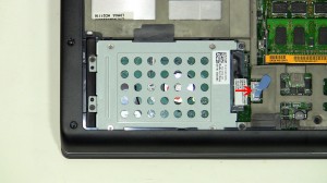
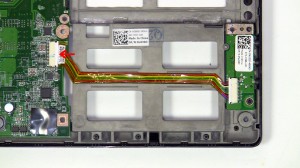
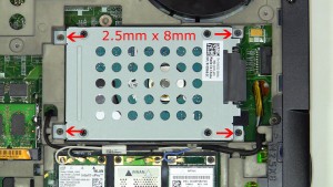
Step 7
- Disconnect the hard drive adapter connector from the motherboard.
- Remove the hard drive screws (4 x M2.5 x 8mm).
Step 8
- Remove the hard drive screws and lift the hard drive out of the laptop (4 x M2.5 x 8mm).
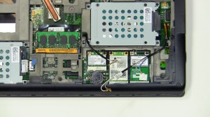
Step 9
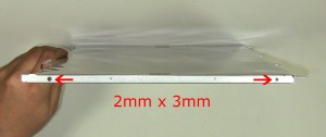
- Unplug the wireless antenna cables.
- Loosen the antenna cables from the routing on the bottom of the laptop.
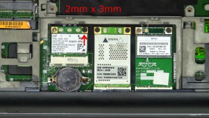
Step 10
- Remove the screw (1 x M2 x 3mm).
- Slide the WLAN card out of the card slot and remove it from the laptop.
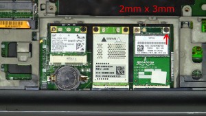
Step 11
- Remove the screw (1 x M2 x 3mm).
- Slide the WPAN card out of the card slot and remove it from the laptop.
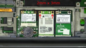
Step 12
- Remove the screw (2 x M2 x 3mm).
- Slide the WWAN card out of the card slot and remove it from the laptop.

Step 13
- Remove the screw under the battery (1 x M2.5 x 5mm).
- Unscrew the base screws (9 x M2.5 x 8mm).
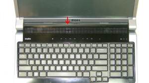
Step 14
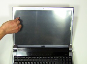
- Turn the laptop over and open it up.
- Starting at the back, carefully lift up to unsnap media cover.
Step 15
- Lay the media cover on to the keyboard and unplug the media cable.
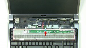
Step 16
- Starting at the top edges of the keyboard bezel, carefully lift it up and unsnap it working your way around the keyboard.
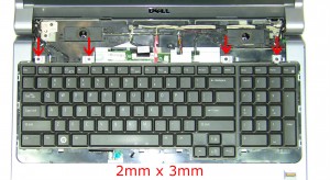
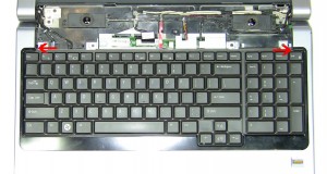
Step 17
- Remove the keyboard screws (4 x M2 x 3mm).
Step 18
- Lift the keyboard away from the base and flip it over.
- If your keyboard is back-lit, you will need to unplug the back light cable. If not skip this step.**Note- If you would like to upgrade to a back-lit keyboard, all of the motherboards for this model already have the back light cable connection.
Step 19
- Unplug the keyboard cable.
Step 20
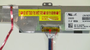
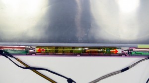
- On the top of the laptop, pull the antenna cables through the motherboard and loosen them from the routing channels on the palm rest.
- Unplug the 3 display cables and loosen them from the routing channels on the palm rest.
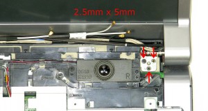
Step 21
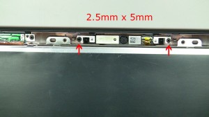
- Remove the screws on the right hinge (3 x M2.5 x 5mm).
- Remove the screws on the left hinge (3 x M2.5 x 5mm).
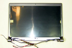
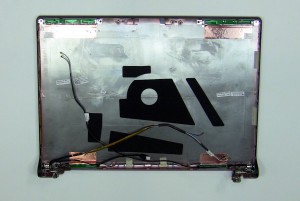
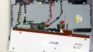
Step 22
- Lift the display assembly away from the laptop base.
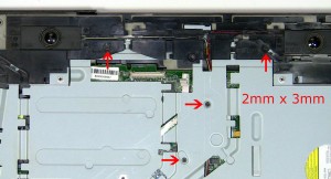
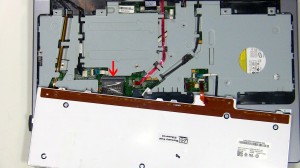
Step 23
- Unscrew the palmrest screws (4 x M2 x 3mm).
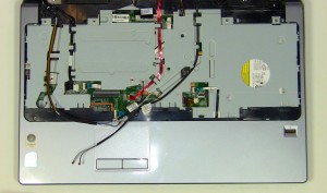
Step 24
- Unplug the 4 palmrest cables.
- Starting at the top center, carefully lift up the palmrest and remove it from the laptop base.
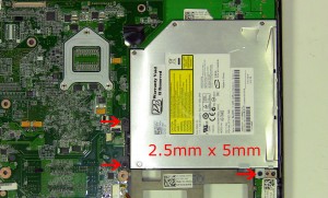
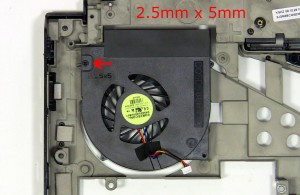
Step 25
- Unscrew the optical drive screws (3 x M2.5 x 5mm).
- Carefully lift the optical drive up away from the motherboard.
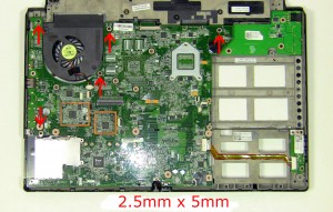
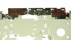
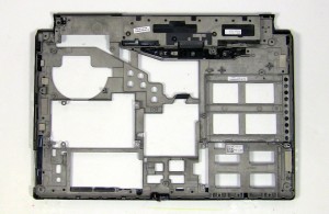
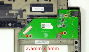
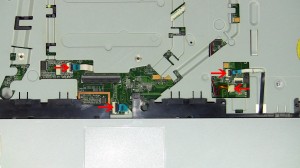
Step 26
- Remove the motherboard screws (5 x M2.5 x 5mm).
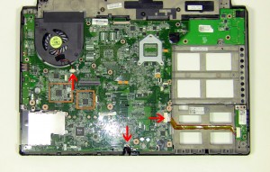
Step 27
- Unplug the 3 cables.
- Lift the motherboard away from the base.
Studio 1737 Mouse Button
Studio 1737 Mouse Button
|
|
Eligible for $5.00 1st Class Shipping. In Stock
Eligible for $5.00 1st Class Shipping. In Stock
Eligible for $5.00 1st Class Shipping. Only 0 left in stock - order soon. DIY Discount - Parts-People.com offers 5% off to all DO-IT-YOURSELFERS!
Use this coupon code to save 5% off these parts DIYM514
|