 Laptop & Tablet Parts
 Desktop & All-in-one Parts
 Dell Server Parts


In this Dell laptop tutorial we are going to show you how to install and replace the CPU Processor on your Dell Inspiron 6400 / E1505 laptop. These installation instructions have be made into 13 easy to follow printable steps. We have also create a video tutorial that shows you how to install your Dell Inspiron 6400 / E1505 CPU Processor.
Before you begin
 Please take the time read the following safety guidelines when working on static sensitive electrical components.
Dell repair manual service precautions
Tools needed for this laptop repair
- 1 x small phillips head screw driver
- 1 x small plastic scribe
Inspiron E1505 CPU CPU
Inspiron E1505 CPU Processor
|
Eligible for $5.00 1st Class Shipping. In Stock 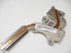
Eligible for $5.00 1st Class Shipping. In Stock 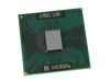
Eligible for $5.00 1st Class Shipping. Only 2 left in stock - order soon. DIY Discount - Parts-People.com offers 5% off to all DO-IT-YOURSELFERS!
Use this coupon code to save 5% off these parts DIYM514
|
Video tutorial repair manual
Installation and Removal Instructions
Dell Inspiron 6400 / E1505 CPU Processor
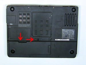
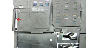
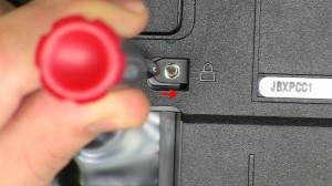
Step 1
- On the bottom of the laptop, slide the battery latch to the right and lift the battery out.
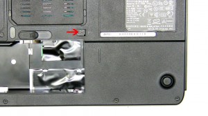
Step 2
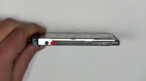
- Remove the 2.5mm x 8mm screw.
- Using a screw driver slide the optical drive out of the laptop.
Step 3
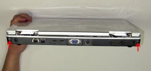
- On the bottom of the laptop remove the (13) 2.5mm x 8mm bottom base screws.
- On the back of the laptop remove the (2) 2.5mm x 8mm Hinge screws.
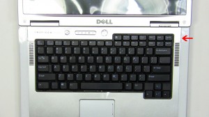
Step 4
- Open the laptop display as far as possible.
- On the right side of the power button, place a flat head screw driver into the slot and carefully pry up the power button cover.
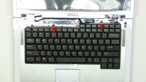
Step 5
- Remove the (2) 2.5mm x 5mm screws.
- Carefully lift the keyboard up and place it onto the LCD screen to reveal the keyboard cable connection.
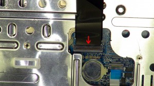
Step 6
- Pivot the keyboard cable latch up and remove the cable.
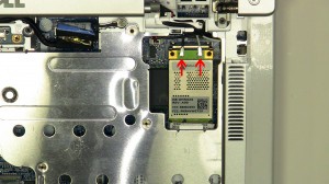
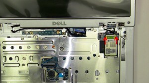
Step 7
- Unplug the wireless antenna cables.
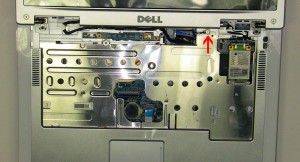
Step 8
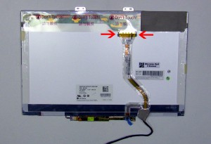
- Loosen the LCD cable ground screw.
- Unplug the LCD cable.
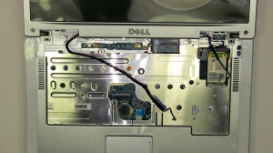
Step 9
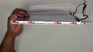
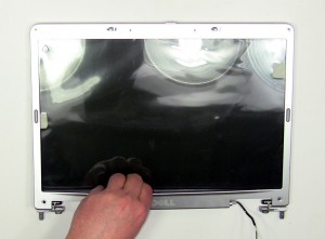
- Loosen the LCD cable and antenna wires from the routing channels.
- Remove the (2) 2.5mm x 5mm hinge screws.
- Lift the display assembly from the laptop base.
Step 10
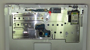
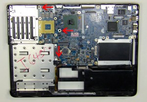
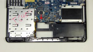
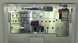
- Loosen the palm rest captive screw. It is attached to the palm rest so you will not be able to fully remove it.
- Unplug the touch pad cable and the stand by switch.
- Carefully unsnap the palm rest from the laptop base.
Step 11
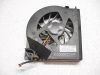
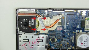
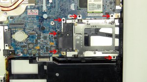
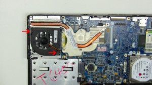
- Loosen the 4 heat sink screws.
- Carefully lift the heat sink away from the motherboard.
Step 12
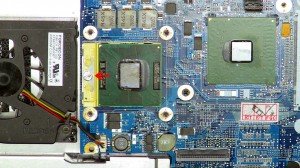
- Turn the CPU locking screw approximately 180 degrees, counterclockwise.
- Lift the CPU out of the CPU socket.
Step 13
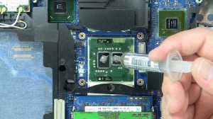
- Installation note 1: Make sure to replace thermal compound or thermal pads on the CPU and heatsink.
- Installation note 2: Tighten the heatsink screws in the order listed on the heatsink.
- **This image is used only as an example.**
Inspiron E1505 CPU CPU
Inspiron E1505 CPU Processor
|
|
Eligible for $5.00 1st Class Shipping. In Stock
Eligible for $5.00 1st Class Shipping. In Stock
Eligible for $5.00 1st Class Shipping. Only 2 left in stock - order soon. DIY Discount - Parts-People.com offers 5% off to all DO-IT-YOURSELFERS!
Use this coupon code to save 5% off these parts DIYM514
|


One Response to Dell Inspiron 6400 E1505 CPU Processor Removal and Installation