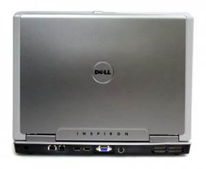
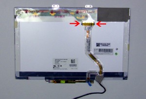
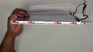
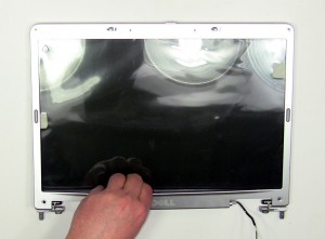
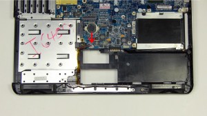
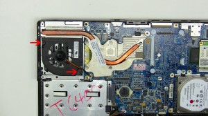
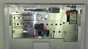
In this Dell laptop tutorial we are going to show you how to install and replace the Express Card Slot Assembly on your Dell Inspiron 6400 / E1505 laptop. These installation instructions have be made into 11 easy to follow printable steps. We have also create a video tutorial that shows you how to install your Dell Inspiron 6400 / E1505 Express Card Slot Assembly.
Before you begin

Dell repair manual service precautions
Tools needed for this laptop repair
- 1 x small phillips head screw driver
- 1 x small plastic scribe
|
|
DIY Discount - Parts-People.com offers 5% off to all DO-IT-YOURSELFERS!
Use this coupon code to save 5% off these parts DIYM514
|
Video tutorial repair manual
Installation and Removal Instructions
Dell Inspiron 6400 / E1505 Express Card Slot Assembly
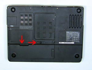

Step 1
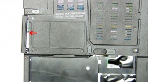
- On the bottom of the laptop, slide the battery latch to the right and lift the battery out.
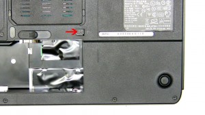

Step 2
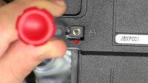
- Remove the 2.5mm x 8mm screw.
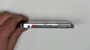
- Using a screw driver slide the optical drive out of the laptop.
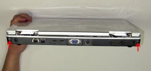

Step 3
- On the bottom of the laptop remove the (13) 2.5mm x 8mm bottom base screws.
- On the back of the laptop remove the (2) 2.5mm x 8mm Hinge screws.
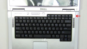

Step 4
- Open the laptop display as far as possible.
- On the right side of the power button, place a flat head screw driver into the slot and carefully pry up the power button cover.
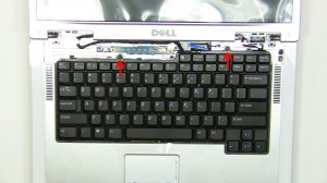

Step 5
- Remove the (2) 2.5mm x 5mm screws.
- Carefully lift the keyboard up and place it onto the LCD screen to reveal the keyboard cable connection.
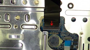

Step 6
- Pivot the keyboard cable latch up and remove the cable.
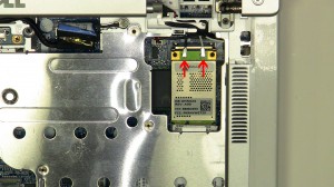

Step 7
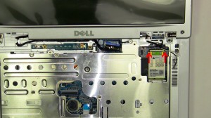
- Unplug the wireless antenna cables.
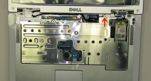

Step 8
- Loosen the LCD cable ground screw.
- Unplug the LCD cable.
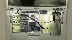

Step 9
- Loosen the LCD cable and antenna wires from the routing channels.
- Remove the (2) 2.5mm x 5mm hinge screws.
- Lift the display assembly from the laptop base.
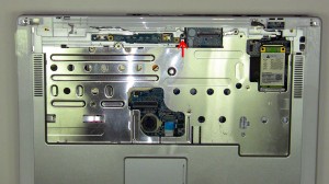

Step 10
- Loosen the palm rest captive screw. It is attached to the palm rest so you will not be able to fully remove it.
- Unplug the touch pad cable and the stand by switch.
- Carefully unsnap the palm rest from the laptop base.
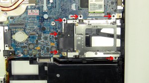

Step 11
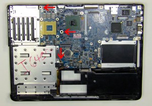
- Remove the (6) 2.5mm x 5mm screws.
- Lift the express card slot assembly away from the motherboard.
|
|
DIY Discount - Parts-People.com offers 5% off to all DO-IT-YOURSELFERS!
Use this coupon code to save 5% off these parts DIYM514
|

 Laptop & Tablet Parts