Dell Latitude E5530 (P28G-001) DC Jack Removal and Installation


In this Dell laptop tutorial we are going to show you how to install and replace the DC Jack on your Latitude E5530 (P28G-001) laptop. These installation instructions have be made into 20 easy to follow printable steps. We have also create a video tutorial that shows you how to install your Latitude E5530 (P28G-001) DC Jack.

Before you begin
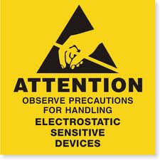
Please take the time read the following safety guidelines when working on static sensitive electrical components.
Dell repair manual service precautions

Tools needed for this laptop repair

  • 1 x small phillips head screwdriver
  • 1 x small plastic scribe
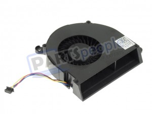
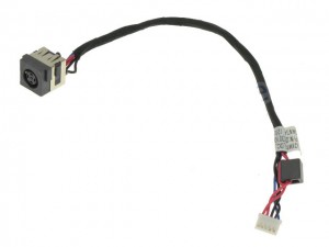
Latitude E5530 DC Jack

Dell Laptop Replacement Parts Needed

DIY Discount - Parts-People.com offers 5% off to all DO-IT-YOURSELFERS!
Use this coupon code to save 5% off these parts
DIYM514
Latitude E5530 DC Jack

Video tutorial repair manual


Installation and Removal Instructions
Latitude E5530 (P28G-001) DC Jack
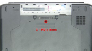
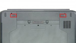
Slide the latches over to unlock the battery.

Step 1

  • Slide the latches over to unlock the battery.
  • Lift the Battery out of the laptop.
Slide the latches over to unlock the battery.Lift the Battery out of the laptop.Slide the latches over to unlock the battery.
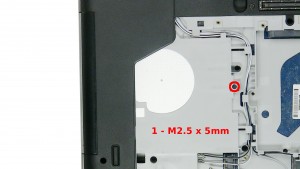
Remove the 1 - M2 x 8mm keyboard screw.

Step 2

Remove the 1 - M2 x 8mm keyboard screw.Remove the 2 - M2.5 x 5mm screws.Remove the Access Door.Remove the 1 - M2 x 8mm keyboard screw.
Remove the 1 - M2.5 x 5mm screw.

Step 3

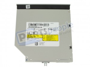
Remove the 1 - M2.5 x 5mm screw.Slide the DVD Optical Drive out of the laptop.Remove the 1 - M2.5 x 5mm screw.
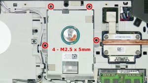
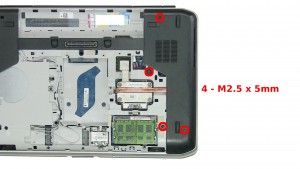
Remove the 4 - M2.5 x 5mm screws.

Step 4

  • Remove the 4 - M2.5 x 5mm screws.
  • Use the pull tab to slide the Hard Drive down and unseat it from the motherboard.
Remove the 4 - M2.5 x 5mm screws.Use the pull tab to slide the Hard Drive down and unseat it from the motherboard.Remove the 4 - M2.5 x 5mm screws.Remove the 4 - M2.5 x 5mm screws.
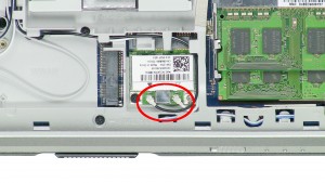
Unplug & loosen the antenna cables.

Step 5

  • Unplug & loosen the antenna cables.
  • Remove the 1 - M2 x 3mm screw.
  • Remove the WLAN Card.
Unplug & loosen the antenna cables.Remove the 1 - M2 x 3mm screw.Remove the WLAN Card.Unplug & loosen the antenna cables.
Remove the 4 - M2.5 x 5mm screws.

Step 6

Remove the 4 - M2.5 x 5mm screws.Remove the CPU Access Door.Remove the 4 - M2.5 x 5mm screws.
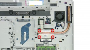
Remove the Heatsink Screws.

Step 7

  • Remove the Heatsink Screws.
  • Remove the Heatsink.
  • ***Replace thermal pads & compound before reinstalling the heatsink.***
Remove the Heatsink Screws.Remove the Heatsink.***Replace thermal pads & compound before reinstalling the heatsink.***
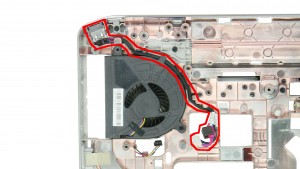
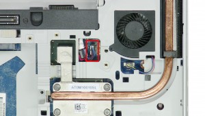
Unplug the DC jack cable.

Step 8

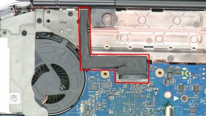
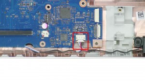
  • Unplug the DC jack cable.
  • Unplug the fan cable.
Unplug the DC jack cable.Unplug the fan cable.
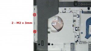
Remove the 2 - M2 x 3mm screws under the optical drive.

Step 9

Remove the 2 - M2 x 3mm screws under the optical drive.Remove the 5 - M2.5 x 8mm screws.Remove the 5 - M2.5 x 5mm screws.
Turn the laptop over & open it up.

Step 10

  • Turn the laptop over & open it up.
  • Unsnap & remove the Keyboard Bezel.
Turn the laptop over & open it up.Unsnap & remove the Keyboard Bezel.
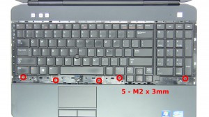
Remove the 5 - M2 x 3mm screws.

Step 11

  • Remove the 5 - M2 x 3mm screws.
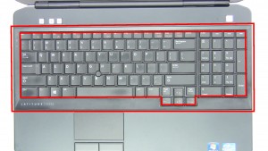
  • Lift the keyboard & turn it over.
Remove the 5 - M2 x 3mm screws.Lift the keyboard & turn it over.
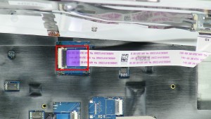
Unplug the keyboard cable.

Step 12

  • Unplug the keyboard cable.
  • Remove the Keyboard.
Unplug the keyboard cable.Remove the Keyboard.
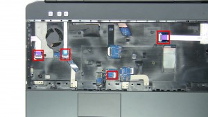
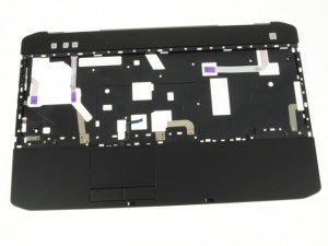
Unplug the palmrest cables.

Step 13

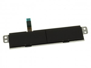
Unplug the palmrest cables.Remove the 5 - M2.5 x 8mm screws.Remove the Palmrest Touchpad.Unplug the palmrest cables.
Unplug the LCD cable.

Step 14

  • Unplug the LCD cable.
  • Pull the antenna cables through the motherboard.
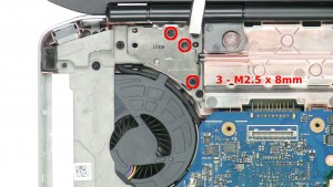
Unplug the LCD cable.Pull the antenna cables through the motherboard.
Remove the 3 - M2.5 x 8mm left hinge screws.

Step 15

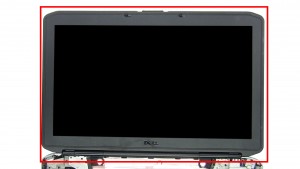
Remove the 3 - M2.5 x 8mm left hinge screws.Remove the 3 - M2.5 x 8mm right hinge screwsRemove the LCD Display Assembly.
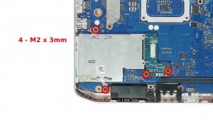
Remove the 4 - M2 x 3mm screws.

Step 16

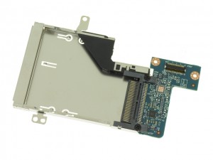
Remove the 4 - M2 x 3mm screws.Remove the ExpressCard Reader.Remove the 4 - M2 x 3mm screws.
Unplug the speaker cable.

Step 17

  • Unplug the speaker cable.
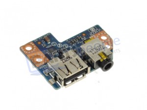
  • Unplug the USB audio circuit board cable.
Unplug the speaker cable.Unplug the USB audio circuit board cable.
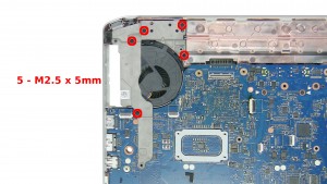
Remove the 5 - M2.5 x 5mm screws.

Step 18

Remove the 5 - M2.5 x 5mm screws.Remove the Left Support Bracket.Remove the 5 - M2.5 x 5mm screws.
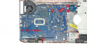
Remove the 6 - M2 x 3mm screws.

Step 19

Remove the 6 - M2 x 3mm screws.Remove the Motherboard.Remove the 6 - M2 x 3mm screws.
Remove the DC Jack.

Step 20

Remove the DC Jack.Remove the DC Jack.
Latitude E5530 DC Jack

Dell Laptop Replacement Parts Needed
DIY Discount - Parts-People.com offers 5% off to all DO-IT-YOURSELFERS!
Use this coupon code to save 5% off these parts
DIYM514
Latitude E5530 DC Jack

Topics: Dell Latitude Repair Manuals Dell Laptop Repair Dell Repair Manuals DC Jack Latitude E5530

Join the conversation!

Leave a Reply

Your email address will not be published. Required fields are marked *

This site uses Akismet to reduce spam. Learn how your comment data is processed.