Laptop & Tablet Parts
 Desktop & All-in-one Parts
 Dell Server Parts


In this Dell laptop tutorial we are going to show you how to install and replace the LCD Screen on your Dell Latitude 11-5175 (T04E001) laptop. These installation instructions have be made into 14 easy to follow printable steps. We have also create a video tutorial that shows you how to install your Dell Latitude 11-5175 (T04E001) LCD Screen.
Before you begin
 Please take the time read the following safety guidelines when working on static sensitive electrical components.
Dell repair manual service precautions
Tools needed for this laptop repair
- 1 x small phillips head screwdriver
- 1 x small plastic scribe
Latitude 5175 LCD Screen
Latitude 11 5175 LCD Screen
|
$59.95
Dell Latitude 11 (5175) Tablet 10.8" FHD Touchscreen LED LCD Screen Display Assembly - WWAN - 751XR Eligible for $5.99 Economy Shipping. Only 2 left in stock - order soon. 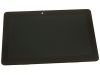
$59.95
Dell Latitude 11 (5175) Tablet 10.8" FHD Touchscreen LED LCD Screen Display Assembly - WLAN - NTM4J Eligible for $5.99 Economy Shipping. Only 18 left in stock - order soon. 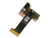
Eligible for $5.99 1st Class Shipping. Only 19 left in stock - order soon. DIY Discount - Parts-People.com offers 5% off to all DO-IT-YOURSELFERS!
Use this coupon code to save 5% off these parts DIYM514
|
Video tutorial repair manual
Installation and Removal Instructions
Dell Latitude 11-5175 (T04E001) LCD Screen
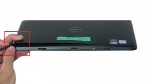
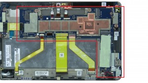
Step 3
- Disconnect docking circuit board cable.
- Unscrew and remove Bottom Base Frame (11 x M1.6 x 3.5mm).

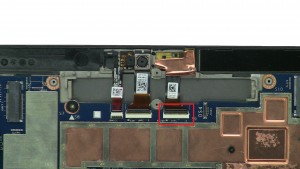
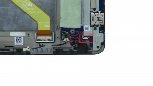
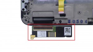
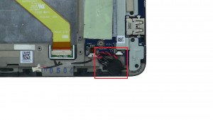
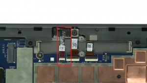
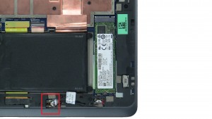
Step 11
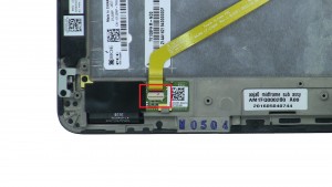
- Disconnect cable from circuit board.
- Unscrew and remove Power Button / Micro SD Card Circuit Board (1 x M2 x 2mm wafer).
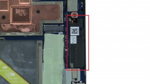
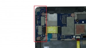
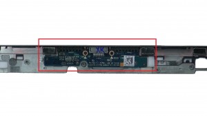
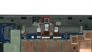
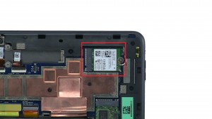
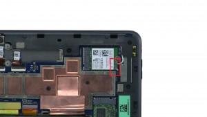
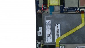
Step 12
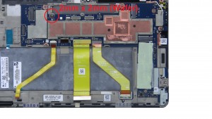
- Disconnect and Unscrew circuit board (1 x M1.6 x 3.5mm).
- Disconnect and remove LCD Circuit Board.
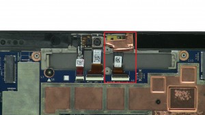
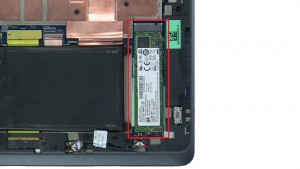
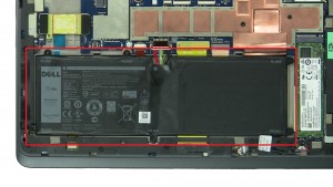
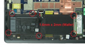
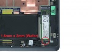
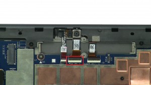
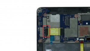
Step 13
- Remove screw from motherboard (1 x M2 x 2mm wafer).
- Unscrew and remove bracket (3 x M1.6 x 3.5mm).
- Disconnect and remove Motherboard.
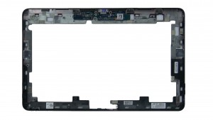
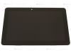
Step 14
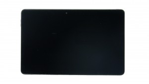
- The remaining piece is the LCD Screen.
Latitude 5175 LCD Screen
Latitude 11 5175 LCD Screen
|
|
$59.95
Dell Latitude 11 (5175) Tablet 10.8" FHD Touchscreen LED LCD Screen Display Assembly - WWAN - 751XR Eligible for $5.99 Economy Shipping. Only 2 left in stock - order soon.
$59.95
Dell Latitude 11 (5175) Tablet 10.8" FHD Touchscreen LED LCD Screen Display Assembly - WLAN - NTM4J Eligible for $5.99 Economy Shipping. Only 18 left in stock - order soon.
Eligible for $5.99 1st Class Shipping. Only 19 left in stock - order soon. DIY Discount - Parts-People.com offers 5% off to all DO-IT-YOURSELFERS!
Use this coupon code to save 5% off these parts DIYM514
|