Laptop & Tablet Parts
 Desktop & All-in-one Parts
 Dell Server Parts


In this Dell laptop tutorial we are going to show you how to install and replace the Express Card Cage on your Dell Inspiron 1525 laptop. These installation instructions have be made into 19 easy to follow printable steps. We have also create a video tutorial that shows you how to install your Dell Inspiron 1525 Express Card Cage.
Before you begin
 Please take the time read the following safety guidelines when working on static sensitive electrical components.
Dell repair manual service precautions
Tools needed for this laptop repair
- 1 x small phillips head screw driver
- 1 x small plastic scribe
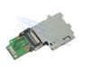
Inspiron 1525 Express Card Cage
Inspiron 1525 Express Card Cage
|
Eligible for $5.00 1st Class Shipping. In Stock 
Eligible for $5.00 1st Class Shipping. Only 6 left in stock - order soon. 
Eligible for $5.00 1st Class Shipping. Only 6 left in stock - order soon. DIY Discount - Parts-People.com offers 5% off to all DO-IT-YOURSELFERS!
Use this coupon code to save 5% off these parts DIYM514
|
Video tutorial repair manual
Installation and Removal Instructions
Dell Inspiron 1525 Express Card Cage
Step 1
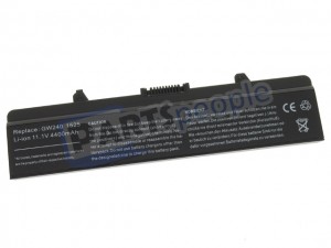
- Remove the battery.
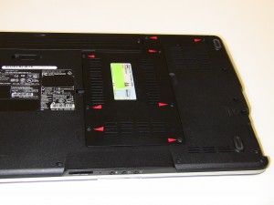
Step 2
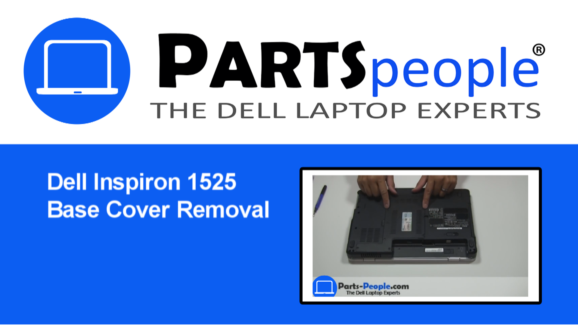
- Access Door
- Unscrew the 8 screws holding the Access Door Cover.
- Remove the cover, starting from right to left.
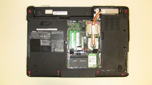
Step 3
- Take out the (7) 2.5mm x 5mm screws.
- Unscrew the (2) 2.5mm x 6mm screws that are holding the Touchpad Palm rest to the base.
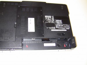
Step 4
- Power Button Cover
- Remove two 2mm x 3mm screws that hold the 1525/1526 center control power button cover to the base of the computer.
Step 5
- Turn the computer over (as if you were typing on it), and fully open the display (approximately 180 degrees, or as far as possible).
- Lift and unsnap the 1525/1526 center control power button cover using a small flat head screw driver or a plastic scribe from the backside of the computer, from right to left. (Be very careful removing it because the plastic can be fragile. (Use caution lifting the power button cover off of the laptop, a cable is attached beneath it that can break easily.)
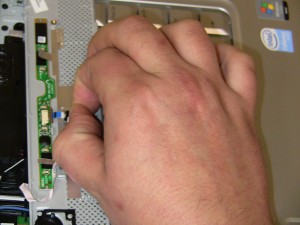
Step 6
- Disconnect the media control cable under the power button cover and lift off the power button cover.
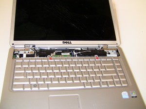
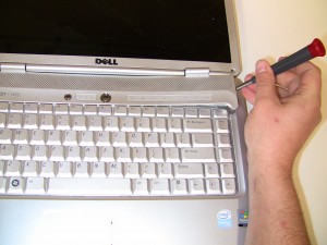
Step 7
- Keyboard Removal
- Unscrew the (2) 2.5mm x 5mmscrews above the keyboard and gently lift up the keyboard to reveal the ribbon cable. Be careful lifting the keyboard because it is very easy to cause damage to the ribbon cable or the motherboard connector. (If the motherboard connector breaks, it is very hard to find replacements for them without replacing the entire motherboard.)
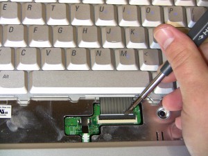
Step 8
- Lift the keyboard cable connector latch and remove the keyboard ribbon cable and keyboard.
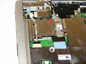
Step 9
- Bluetooth Card
- Remove the Bluetooth card by unscrewing the 2mm x 3mm retaining screw.
- Unplug the cable.
- Slide the cable out and unhook it from the motherboard.
Step 10
- LCD Display Assembly
- Unplug the display cable from the motherboard.
- Unplug the camera cable from the motherboard.
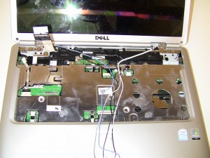
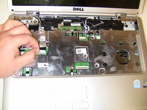
Step 11
- Slide antenna wires out of the motherboard and loosen them from the top of the laptop.
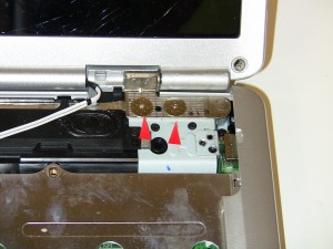
Step 12
- Unscrew the (2) 2.5mm x 3mm – 10 mm wafer hinge screws from the left display hinge.
- Unscrew the (2) 2.5mm x 3mm – 10 mm wafer hinge screws from the right display hinge.
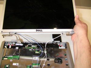
Step 13
- Lift the 1525/1526 LCD display assembly up away from the base.
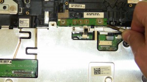
Step 14
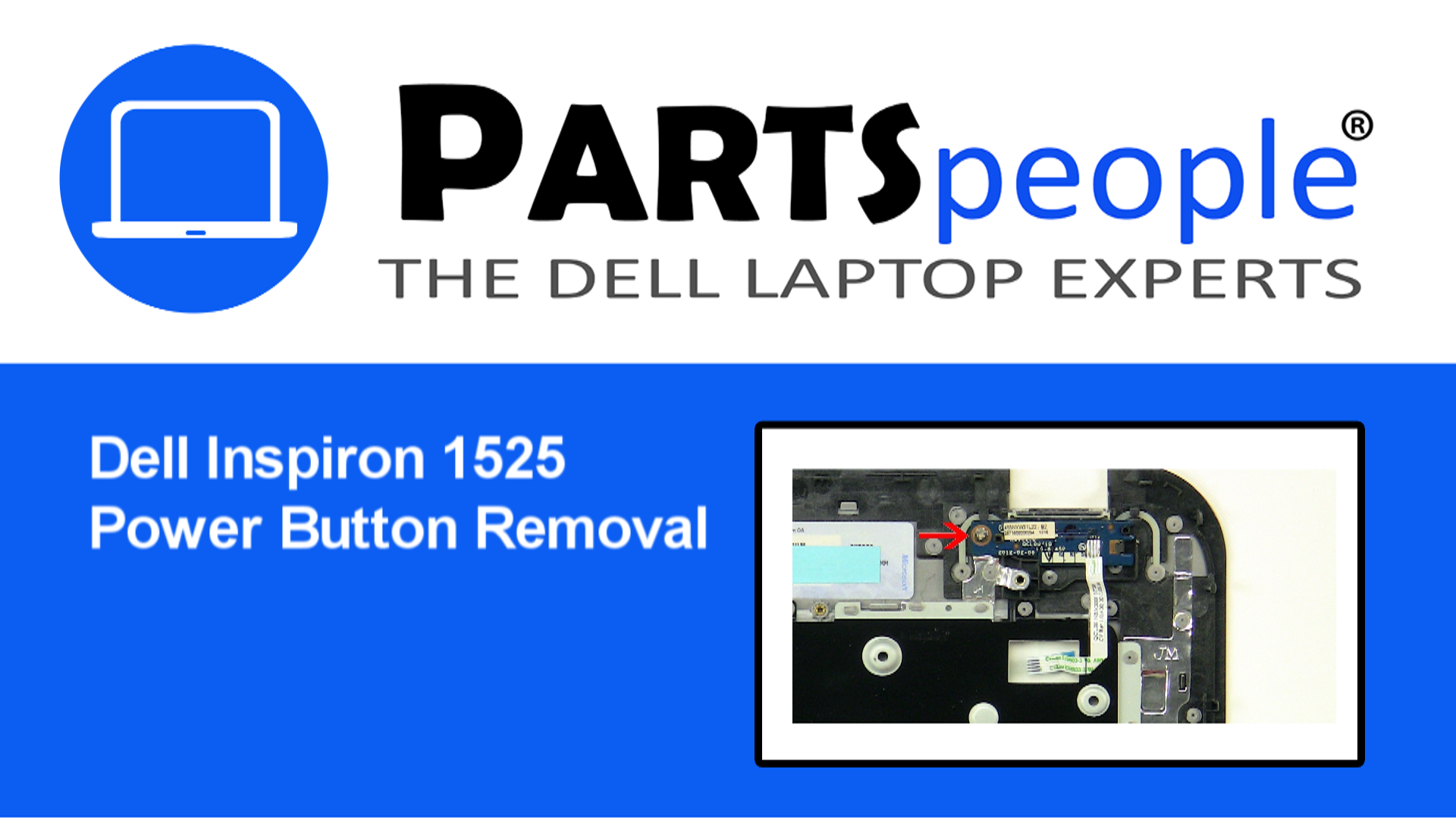
- Power Button Circuit Board
- Unplug the power button circuit board cable from the motherboard and lift the board off of the base. The power button board may have glue on it so be careful prying it up.
Step 15
- Unplug the Speaker cable from the motherboard.
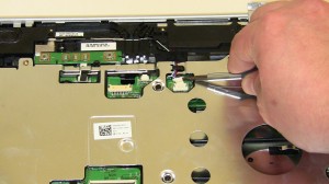
Step 16
- Remove the remaining (2) 2.5mm x 5mm and the (1) 2.5mm x 3mm – 10mm wafer screws.
Step 17
- Unplug the LED light cable.
- Unplug the touchpad cable from the motherboard.
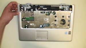
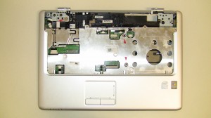
Step 18
- Carefully lift the touchpad palm rest off of the base, starting from the upper left corner, unsnapping it along the edges.
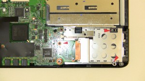
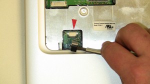
Step 19
- Unscrew (3) 2mm x 3mm screws on the express card slot.
- Pull the express card slot assembly away form the base and it’s motherboard connector.
Inspiron 1525 Express Card Cage
Inspiron 1525 Express Card Cage
|
|
Eligible for $5.00 1st Class Shipping. In Stock
Eligible for $5.00 1st Class Shipping. Only 6 left in stock - order soon.
Eligible for $5.00 1st Class Shipping. Only 6 left in stock - order soon. DIY Discount - Parts-People.com offers 5% off to all DO-IT-YOURSELFERS!
Use this coupon code to save 5% off these parts DIYM514
|