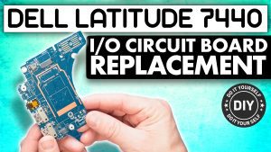
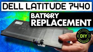
In this Dell laptop tutorial we are going to show you how to install and replace the I/O Circuit Board on your Latitude 7440 laptop. These installation instructions have been made into 7 easy to follow printable steps. We have also created a video tutorial that shows you how to install your Latitude 7440 I/O Circuit Board.
Before you begin

Dell repair manual service precautions
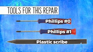
Tools needed for this laptop repair
- 1 x Phillips #0 screwdriver
- 1 x Phillips #1 screwdriver
- 1 x small plastic scribe
Latitude 7440 I O Circuit Board
Latitude 7440 I O Circuit Board
|
|
DIY Discount - Parts-People.com offers 5% off to all DO-IT-YOURSELFERS!
Use this coupon code to save 5% off these parts DIYM514
|
Video tutorial repair manual
Installation and Removal Instructions
Latitude 7440 I/O Circuit Board


Step 1
- Before you begin: If you need help at any point, you can always contact Parts-People Laptop Repair Department for help with your diagnosis or repair.

Step 2
- Use a Phillips #1 Screwdriver to loosen the Bottom Base Cover screws (8 x captive screws).
- Use a Plastic Scribe to pry apart and remove the Bottom Base Cover.
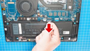

Step 3
- Disconnect the Battery.
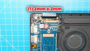

Step 4
- Unscrew and remove the power button cable bracket (1 x M2 x 2mm).
- Disconnect the power button cable.
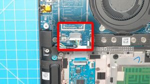

Step 5
- Disconnect the speaker cable.
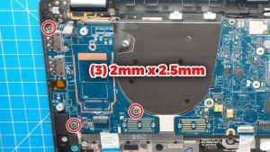

Step 7
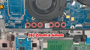
- Unscrew and remove the I/O Circuit Board (3 x 2mm x 2.5mm).
- ***FOLLOW THESE STEPS IN REVERSE TO REINSTALL YOUR PART.
Latitude 7440 I O Circuit Board
Latitude 7440 I O Circuit Board
|
|
DIY Discount - Parts-People.com offers 5% off to all DO-IT-YOURSELFERS!
Use this coupon code to save 5% off these parts DIYM514
|

 Laptop & Tablet Parts