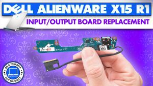
In this Dell laptop tutorial we are going to show you how to install and replace the I/O Circuit Board on your Alienware x15 R1 laptop. These installation instructions have been made into 23 easy to follow printable steps. We have also created a video tutorial that shows you how to install your Alienware x15 R1 I/O Circuit Board.
Before you begin
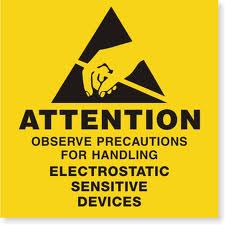

Dell repair manual service precautions
Tools needed for this laptop repair
- 1 x Phillips #0 screwdriver
- 1 x Phillips #1 screwdriver
- 1 x small plastic scribe
Alienware x15 R1 I O Circuit Board
Alienware x15 R1 I O Circuit Board
|
|
DIY Discount - Parts-People.com offers 5% off to all DO-IT-YOURSELFERS!
Use this coupon code to save 5% off these parts DIYM514
|
Video tutorial repair manual
Installation and Removal Instructions
Alienware x15 R1 I/O Circuit Board


Step 1
- Before you begin: If you need help at any point, you can always contact Parts-People Repair Department for help with your diagnosis or repair.


Step 2
- Use a Phillips Screwdriver to loosen the Bottom Base Cover screws (4 x M2.5 x 7mm) (2 x captive screws).
- Use a Plastic Scribe to pry apart and remove the Bottom Base Cover.

Step 3
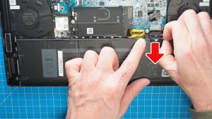
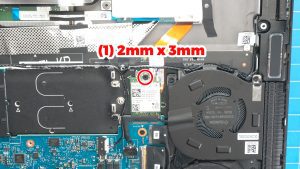
- To protect your laptop from static discharge, disconnect the Battery.

Step 4

Step 5
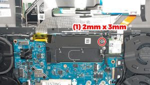
- Unscrew and slide out the SSD thermal shield (1 x M2 x 3mm).
- Separate the M.2 NVMe SSD from the thermal shield.

Step 7
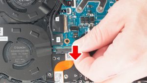
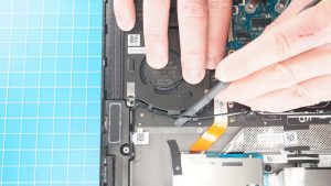
- Disconnect the left and right cooling fans.

Step 8
- Remove the speaker cable and antenna cable from the routing guides on the left cooling fan.
- Unscrew and remove the Left Cooling Fan (3 x M2 x 4mm).

Step 9
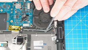
- Remove the speaker cable and the antenna cable from the routing guides on the right cooling fan.
- Unscrew and remove the Right Cooling Fan (3 x M2 x 4mm).

Step 10
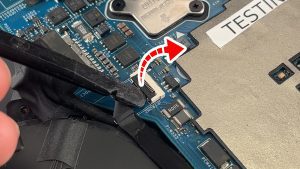
- Unclip the locking tab to release the rear I/O cover cable.
- Disconnect the rear I/O cover cable.

Step 11
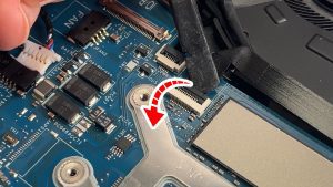
- Unclip the locking tab to release the rear I/O cover cable.
- Disconnect the rear I/O cover cable.
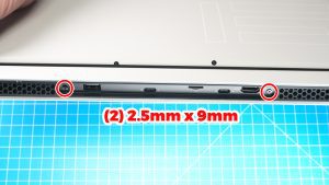

Step 12
- Unscrew and slide off the rear I/O cover (2 x 2.5mm x 9mm).
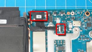

Step 13
- Disconnect the left LCD cables.
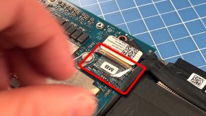

Step 14
- Peel off the protective tape.
- Unclip the locking tab.
- Disconnect the right LCD cable.
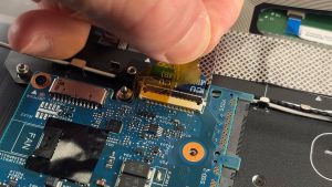

Step 15
- Peel away the tape to expose the the keyboard controller cable connector.
- Unclip the locking tab to disconnect the keyboard controller board.
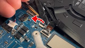

Step 16
- Unclip the locking tab and disconnect the power button cable.
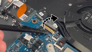

Step 17
- Unclip the locking tab and disconnect the I/O board cable.
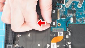

Step 18
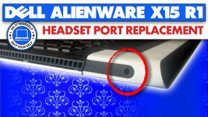
- Disconnect the headset port cable.
- Remove these cables from the routing guide.
- Remove the headset port.
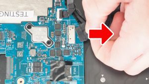

Step 19
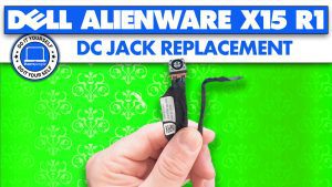
- Disconnect and then unroute the DC jack cable.
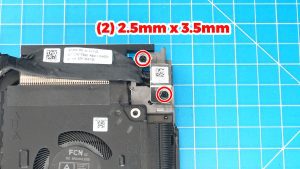

Step 20
- Unscrew and remove the DC jack bracket (2 x 2.5mm x 3.5mm).
- Remove the DC Jack Charging Port.
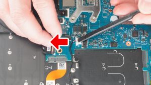

Step 21
- Disconnect the speaker cable.
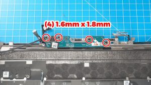

Step 23
- Unscrew and remove the I/O Circuit Board (4 x 1.6mm x 1.8mm).
- ***THE REINSTALLATION PROCESS IS AS SIMPLE AS FOLLOWING THESE STEPS IN REVERSE.
Alienware x15 R1 I O Circuit Board
Alienware x15 R1 I O Circuit Board
|
|
DIY Discount - Parts-People.com offers 5% off to all DO-IT-YOURSELFERS!
Use this coupon code to save 5% off these parts DIYM514
|

 Laptop & Tablet Parts