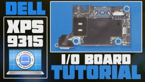
In this Dell laptop tutorial we are going to show you how to install and replace the I/O Circuit Board on your XPS 13 (9315) laptop. These installation instructions have been made into 11 easy to follow printable steps. We have also created a video tutorial that shows you how to install your XPS 13 (9315) I/O Circuit Board.
Before you begin

Dell repair manual service precautions
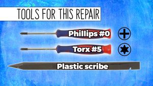
Tools needed for this laptop repair
- 1 x Torx #5 screwdriver
- 1 x Phillips #0 screwdriver
- 1 x small plastic scribe
XPS 9315 I O Circuit Board
XPS 13 9315 I O Circuit Board
|
|
DIY Discount - Parts-People.com offers 5% off to all DO-IT-YOURSELFERS!
Use this coupon code to save 5% off these parts DIYM514
|
Video tutorial repair manual
Installation and Removal Instructions
XPS 13 (9315) I/O Circuit Board


Step 1
- Before you begin: If you need help at any point, you can always contact Parts-People Laptop Repair Department for help with your diagnosis or repair.
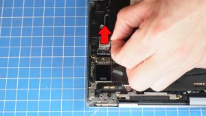

Step 3
- Disconnect the battery cable.
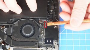

Step 4
- Disconnect the I/O board cable lifting from the outside of the connector as shown.
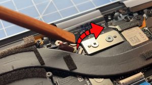

Step 5
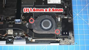
- Unsnap the locking tab and disconnect the cooling fan cable.
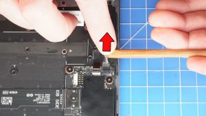

Step 7
- Slide out the speaker cable.
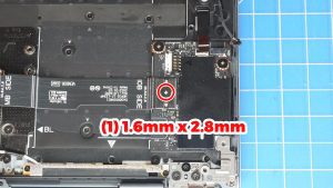

Step 8
- Unscrew and disconnect the I/O circuit board cable.
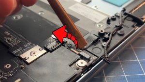

Step 9
- Unsnap the locking tab and disconnect the power button cable.
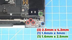

Step 10
- Unscrew and lift the right LCD hinge (3 x 2.5mm x 4.3mm) (1 x 1.6mm x 3mm) (1 x M1.6 x 2.5mm).
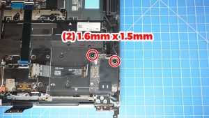

Step 11
- Unscrew and remove the I/O Circuit Board (2 x 1.6mm x 1.5mm)
- ***FOLLOW THE ORIGINAL STEPS IN REVERSE TO REASSEMBLE YOUR LAPTOP.
XPS 9315 I O Circuit Board
XPS 13 9315 I O Circuit Board
|
|
DIY Discount - Parts-People.com offers 5% off to all DO-IT-YOURSELFERS!
Use this coupon code to save 5% off these parts DIYM514
|

 Laptop & Tablet Parts