Laptop & Tablet Parts
 Desktop & All-in-one Parts
 Dell Server Parts


In this Dell laptop tutorial we are going to show you how to install and replace the Motherboard on your Inspiron 14 (7430) 2-In-1 laptop. These installation instructions have been made into 18 easy to follow printable steps. We have also created a video tutorial that shows you how to install your Inspiron 14 (7430) 2-In-1 Motherboard.
Before you begin
 Please take the time read the following safety guidelines when working on static sensitive electrical components.
Dell repair manual service precautions
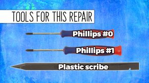
Tools needed for this laptop repair
- 1 x Phillips #0 screwdriver
- 1 x Phillips #1 screwdriver
- 1 x small plastic scribe
Inspiron 7430 2-in-1 Motherboard
Inspiron 14 7430 2-in-1 Motherboard
|

$229.95
Dell Inspiron 14 7430 2-in-1 Motherboard System Board Intel i3-1315U Up To 4.5GHz - 8GB - DGJ1D Eligible for FREE Economy Shipping. Only 4 left in stock - order soon. 
Eligible for $5.00 1st Class Shipping. Only 4 left in stock - order soon. 
Eligible for $5.00 1st Class Shipping. Only 9 left in stock - order soon. DIY Discount - Parts-People.com offers 5% off to all DO-IT-YOURSELFERS!
Use this coupon code to save 5% off these parts DIYM514
|
Video tutorial repair manual
Installation and Removal Instructions
Inspiron 14 (7430) 2-In-1 Motherboard
Step 1
- Before you begin: If you need help at any point, you can always contact Parts-People Motherboard Repair Department for help with your diagnosis or repair.
Step 2
- Unscrew the bottom base cover (3 x captive screws) (4 x M2 x 4mm).
- Use a plastic scribe to separate and remove the Bottom Base Cover.
Step 3
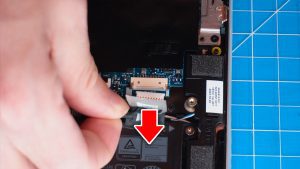
- Disconnect the battery cable.
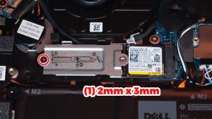
Step 5

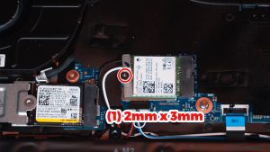
Step 7
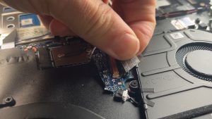
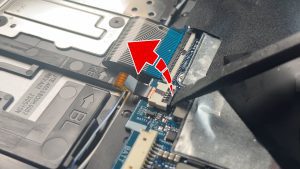
- Peel back the adhesive covering.
- Unclip the locking tab and disconnect the I/O board cable.
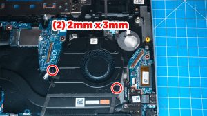
Step 9
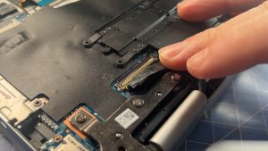
- Unclip the locking tabs and disconnect the keyboard cables.
Step 10
- Unclip the locking tab and disconnect the touchpad cable.
Step 11
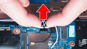
- Disconnect the Speakers.
Step 12
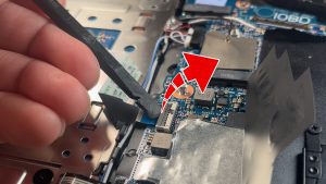
- Peel back the adhesive covering the LCD cable connector.
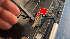
Step 13
- Unsnap the locking tabs and disconnect the LCD cables.

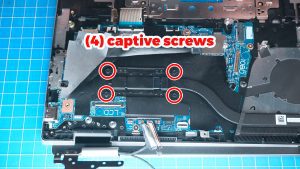
Step 15
- Unscrew and remove the Heatsink (4 x captive screws).

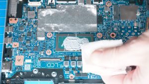
Step 17
- BEFORE REPLACING HEATSINK: Wipe away any old thermal paste from the CPU and heatsink.
- ***NOTE: Make sure to not touch the heat transfer areas on the heatsink and processors. The oils on your skin can reduce the heat transfer capability of the thermal paste.
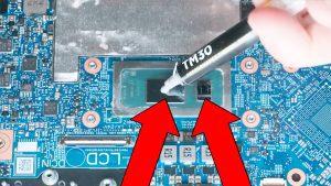
Step 18
- Apply a small amount of new thermal paste to the processors.
- Replace the heatsink.
- ***FOLLOW THE ORIGINAL STEPS IN REVERSE TO REASSEMBLE YOUR LAPTOP.
Inspiron 7430 2-in-1 Motherboard
Inspiron 14 7430 2-in-1 Motherboard
|
|
$229.95
Dell Inspiron 14 7430 2-in-1 Motherboard System Board Intel i3-1315U Up To 4.5GHz - 8GB - DGJ1D Eligible for FREE Economy Shipping. Only 4 left in stock - order soon.
Eligible for $5.00 1st Class Shipping. Only 4 left in stock - order soon.
Eligible for $5.00 1st Class Shipping. Only 9 left in stock - order soon. DIY Discount - Parts-People.com offers 5% off to all DO-IT-YOURSELFERS!
Use this coupon code to save 5% off these parts DIYM514
|