Laptop & Tablet Parts
 Desktop & All-in-one Parts
 Dell Server Parts


In this Dell laptop tutorial we are going to show you how to install and replace the Palmrest Assembly on your Alienware m17 R2 laptop. These installation instructions have been made into 31 easy to follow printable steps. We have also created a video tutorial that shows you how to install your Alienware m17 R2 Palmrest Assembly.
Before you begin
 Please take the time read the following safety guidelines when working on static sensitive electrical components.
Dell repair manual service precautions
Tools needed for this laptop repair
- 1 x Phillips #0 screwdriver
- 1 x small plastic scribe
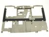
Alienware m17 R2 Palmrest Assembly
Alienware m17 R2 Palmrest Assembly
|
Eligible for $5.00 Economy Shipping. Only 15 left in stock - order soon. 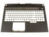
Eligible for $5.00 Economy Shipping. Only 5 left in stock - order soon. 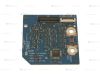
Eligible for $5.00 1st Class Shipping. In Stock DIY Discount - Parts-People.com offers 5% off to all DO-IT-YOURSELFERS!
Use this coupon code to save 5% off these parts DIYM514
|
Video tutorial repair manual
Installation and Removal Instructions
Alienware m17 R2 Palmrest Assembly

Step 1
- Before you begin: If you need help at any point, you can always contact Parts-People Repair Department for help with your diagnosis or repair.

Step 2
- CAUTION: Electrostatic Discharge (ESD) is the build up of static electricity on a person's body. This can cause serious damage to your laptop. You can use an ESD wrist strap or an ESD mat to help prevent this.

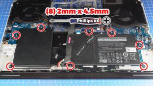
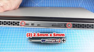
Step 3
- TOOLS FOR THIS REPAIR: Phillips #0 and a Plastic Scribe.
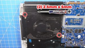
- Unscrew the Bottom Base Cover (2 x M2.5 x 5mm) (6 X captive screws).
- Pry apart and remove the Bottom Base Cover.
Step 4
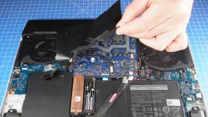
- Peel off the adhesive covering from the motherboard.
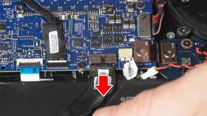
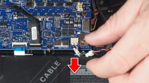
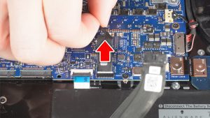
Step 5
- Disconnect the battery cable.
Step 6
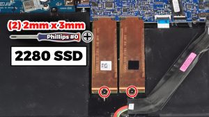
- Remove the SSDs...
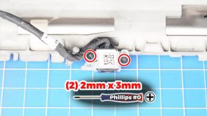
- TO REMOVE THE 2280 M.2 NVME SSDs: Unscrew and remove the thermal brackets (2 x M2 x 3mm).
- Slide out the 2280 SSDs.
- TO REMOVE THE 2230 M.2 NVME SSDs: The process is the same. The only difference is the screw configuration.
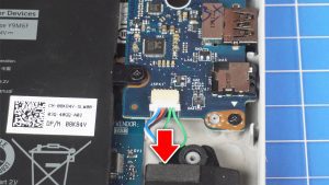
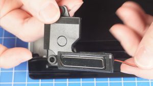
Step 7
- Disconnect the speaker cable.
Step 10
- Disconnect and remove the CMOS battery.
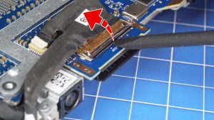
Step 11
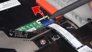
- Disconnect the Rear I/O Cover cable.
Step 13
- Unclip the locking tab and then disconnect the LCD cables.


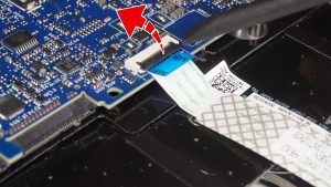
Step 16
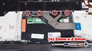
- Unclip the locking tabs and then disconnect the keyboard controller cable from the motherboard.
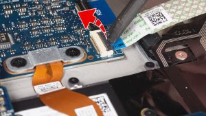
Step 17
- Unclip the locking tabs and then disconnect the keyboard controller cables.
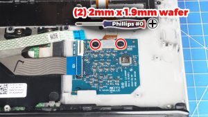
Step 18
- Unscrew and disconnect the keyboard cable (2 X 2mm x 1.9mm wafer).
- Remove the Keyboard Controller Board.
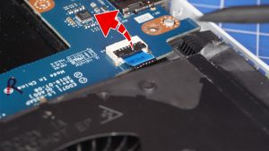
Step 19
- Unclip the locking tab and then disconnect the power button cable.
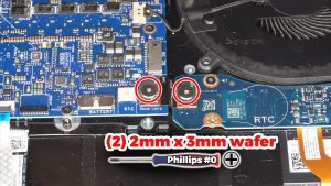
Step 20
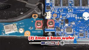
- Unscrew and disconnect the I/O board cable that bridges the right I/O circuit board to the motherboard (2 x M2 x 3mm wafer).
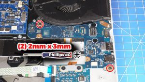
Step 22
- Unscrew and disconnect the I/O board cable that bridges the left I/O circuit board to the motherboard (2 x M2 x 3mm wafer).

Step 24
- Unclip the locking tabs and then disconnect the touchpad cable.
Step 26
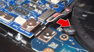
- Disconnect the DC Jack cable.

Step 30
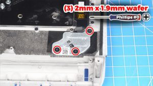
- Unscrew and remove the power button bracket (3 X 2mm x 1.9mm wafer).
- Remove the Power Button.

Step 31
- Unscrew and remove the Keyboard (39 X 1.2mm x 1.6mm) (14 X 1.2mm x 2.1mm).
- The remaining part is the Palmrest Assembly.
- ***FOLLOW THE ORIGINAL STEPS IN REVERSE TO REASSEMBLE YOUR LAPTOP.
Alienware m17 R2 Palmrest Assembly
Alienware m17 R2 Palmrest Assembly
|
|
Eligible for $5.00 Economy Shipping. Only 15 left in stock - order soon.
Eligible for $5.00 Economy Shipping. Only 5 left in stock - order soon.
Eligible for $5.00 1st Class Shipping. In Stock DIY Discount - Parts-People.com offers 5% off to all DO-IT-YOURSELFERS!
Use this coupon code to save 5% off these parts DIYM514
|